Stormwater - Planning Backoffice User Manual
Configuration area for the Stormwater Planning module
1. Introduction
1.1 Application structure
The Stormwater Planning application is divided into two main areas: Planning and Planning Backoffice.
Planning is the operational area where users review the committed configuration and calculated scenario results. It is documented separately in the Stormwater Planning manual.
Planning Backoffice is the configuration area where administrative users prepare the data used by the Planning module. It is documented on this page.
1.2 User roles
The system contains three main user roles.
- System Admin - full administrative access.
- Organization Admin - administrative access within the assigned organization.
- Standard User - regular operational access without Planning Backoffice editing rights.
2. Common user interface elements
2.1 Top bar overview
The top bar contains the standard navigation elements used across the application. These elements allow the user to move between applications, regions, organizations, and profile settings.

Figure 1. Top bar overview with the logo, application name, Region selector, organization name, and user profile button.
2.2 Logo and home page navigation
The logo is located in the upper left corner. Clicking the logo takes the user to the main page.
2.3 Application selector
Next to the logo there is the application name. Clicking the application name opens the application selector menu. This menu allows the user to move between available application areas, for example Planning and Planning Backoffice.
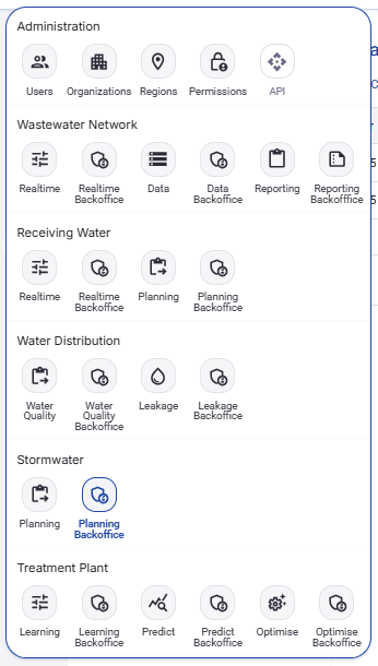
Figure 2. Application selector menu with the available application areas, including Stormwater Planning and Planning Backoffice.
2.4 Region selector
In the top bar, next to the application selector, there is a Region selector. If more than one region is available, the user can select the active region here. If only one region exists in the current application instance, the Region selector is disabled and appears greyed out.
2.5 Organization name
In the upper right area the application shows the name of the organization for the currently logged-in user.
2.6 User profile menu
On the far right there is the user profile button. Clicking it opens the user profile menu. From this menu the user can open the profile page, enter Planning Backoffice if access is available, change the language, change the theme, or log out.
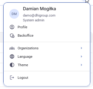
Figure 3. User profile menu with Profile, Backoffice, Organizations, Language, Theme, and Logout actions.
2.7 User profile page and password change
The Profile option opens the user profile page. This page shows the basic account data and contains the Change password action. The password change window opens from that page. The user enters the new password and confirms the change.

Figure 4. User profile page with the Change password action.
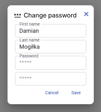
Figure 5. Change password window opened from the user profile page.
2.8 Planning Backoffice entry from the profile menu
If the logged-in user has the required rights, the Planning Backoffice option is visible in the profile menu. Clicking it opens the Planning Backoffice area.
2.9 Language selection
The Language option opens a list of available interface languages.
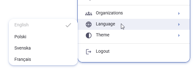
Figure 6. Language selection menu with the available interface languages.
2.10 Theme selection
The Theme option allows the user to switch between Light, Dark, and System. The System option follows the theme settings of the operating system used by the person viewing the application.
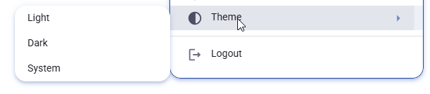
Figure 7. Theme selection menu with Light, Dark, and System options.
2.11 Logout
The last option in the profile menu is Logout. Clicking this option signs the user out of the application.
3. Planning Backoffice overview
3.1 Who can work in Planning Backoffice
Planning Backoffice can be accessed and edited only by Organization Admin and System Admin users. Standard Users do not have access to Planning Backoffice.
3.2 Planning Backoffice navigation
Planning Backoffice navigation is displayed on the left side of the screen. In the current scope, the visible tabs are Catchments, Contaminant types, Land uses, Treatment System Types, Map, and Baseline Scenarios.
When Planning Backoffice is opened, the application goes directly to the Catchments tab.
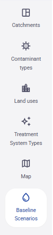
Figure 8. Planning Backoffice navigation sidebar with the tabs included in the current manual.
3.3 System state and the Commit action
Changes made in Planning Backoffice do not take effect in the Planning view until they are committed.
The Commit action is located in the Baseline Scenarios tab. After all required configuration is complete, the user must click Commit so that the Planning view uses the current database state.
If no commit has been performed, the Planning view displays a warning that no data is available.
4. Catchments
4.1 Purpose of the Catchments tab
The Catchments tab is used to define drainage areas in the stormwater network. Each catchment contains one or more subcatchments. The subcatchments hold the area values used later in the planning workflow.
4.2 Catchments overview
The Catchments tab is divided into two main parts. The left side contains the list of catchments and the actions available for this tab. The right side shows the map preview. The lower section shows the Subcatchments table for the currently selected catchment.
The visible actions at the top of the tab are Download template and Upload.
Each catchment row in the list has a context menu opened from the three-dot icon. Each subcatchment row in the table also has its own context menu.
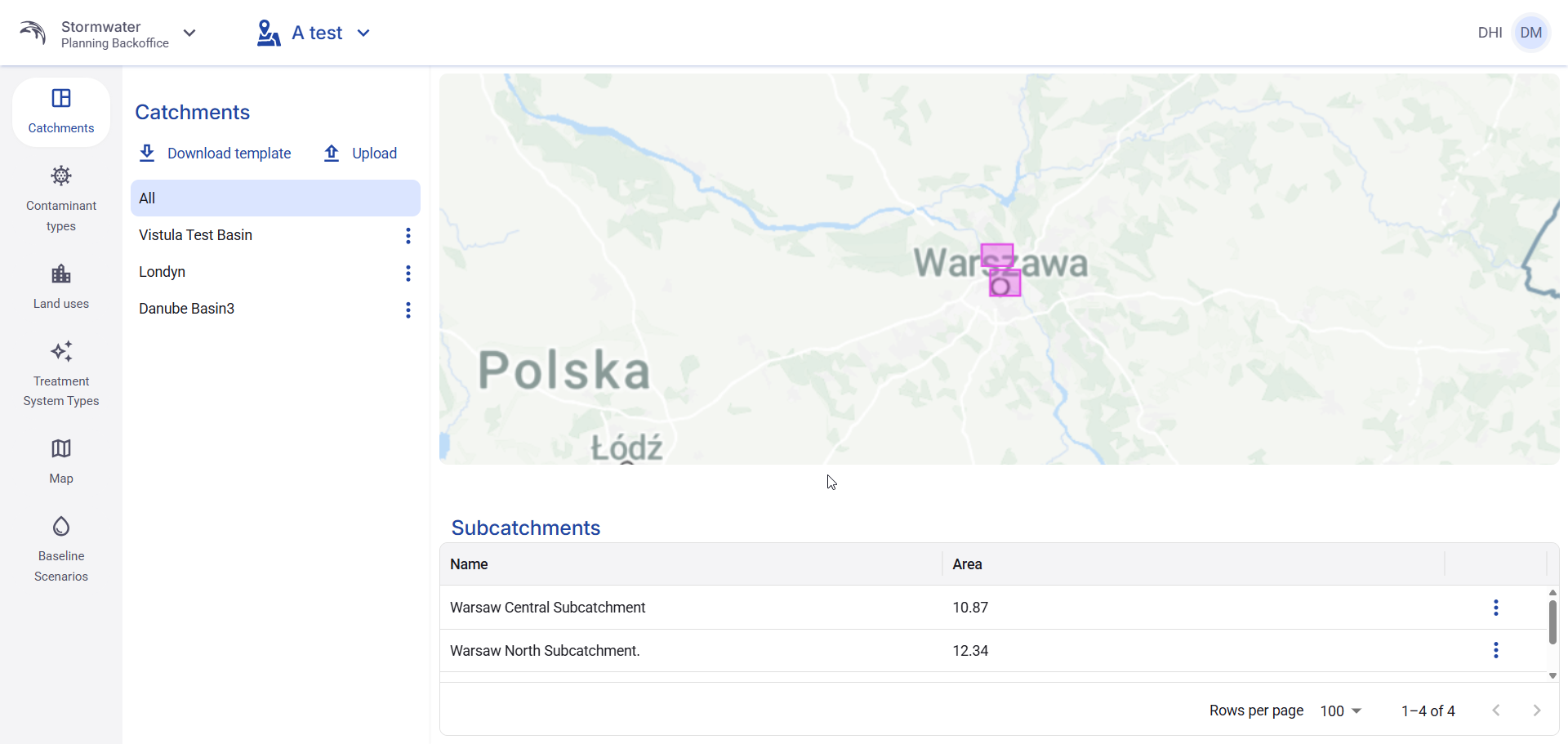
Figure 9. Catchments tab overview with catchment list, map preview, and Subcatchments table.
4.3 Upload catchments
To import catchments, click Upload. The upload window opens and requires two inputs: Format and File.
The available file formats visible in the interface are GeoJson and Shapefile zip.
After selecting the correct format and choosing the file, click Upload to import the data.
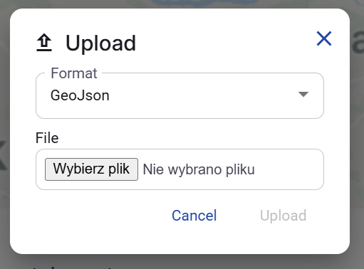
Figure 10. Upload dialog with GeoJson selected.
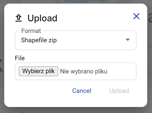
Figure 11. Upload dialog with Shapefile zip selected.
4.4 Download template
To download an import template, click Download template. The dialog allows the user to select the file format before downloading the template.
The available formats visible in the interface are GeoJson and Shapefile zip.
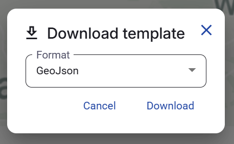
Figure 12. Download template dialog with GeoJson selected.
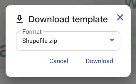
Figure 13. Download template dialog with Shapefile zip selected.
4.5 Edit a catchment
Each catchment has an Edit action in its context menu.
The edit window allows the user to change the Name of the selected catchment. The visible field in this window is Name.
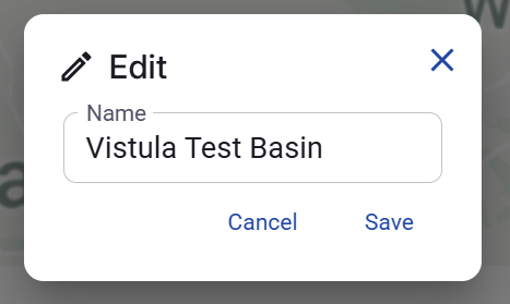
Figure 14. Edit catchment dialog.
4.6 Edit a subcatchment
Each subcatchment row has an Edit action in its context menu.
The edit window allows the user to change two values:
- Name
- Area
The Area field stores the area value of the selected subcatchment.
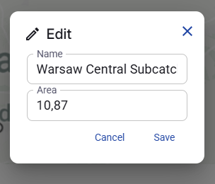
Figure 15. Edit subcatchment dialog with Name and Area fields.
4.7 Delete a subcatchment
Each subcatchment row has a Delete action in its context menu.
A confirmation dialog opens before the deletion is executed.
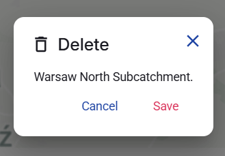
Figure 16. Delete subcatchment confirmation dialog.
4.8 Delete a catchment
Each catchment has a Delete action in its context menu.
A confirmation dialog opens before the deletion is executed.
Deleting a catchment removes the selected catchment from the catchment list. Based on the structure of this tab, the user should treat this action carefully because the selected catchment is the parent object for the subcatchments displayed below it.
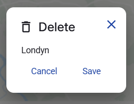
Figure 17. Delete catchment confirmation dialog.
5. Contaminant types
5.1 Purpose of the Contaminant types tab
The Contaminant types tab shows the list of contaminant types available in the Stormwater Planning module. These contaminant types are used in other configuration areas, especially Land uses and Treatment System Types, where the user enters values for each contaminant.
5.2 Contaminant types table
The tab contains a single table with two visible columns: Key and Name. Each row represents one contaminant type available in the system.
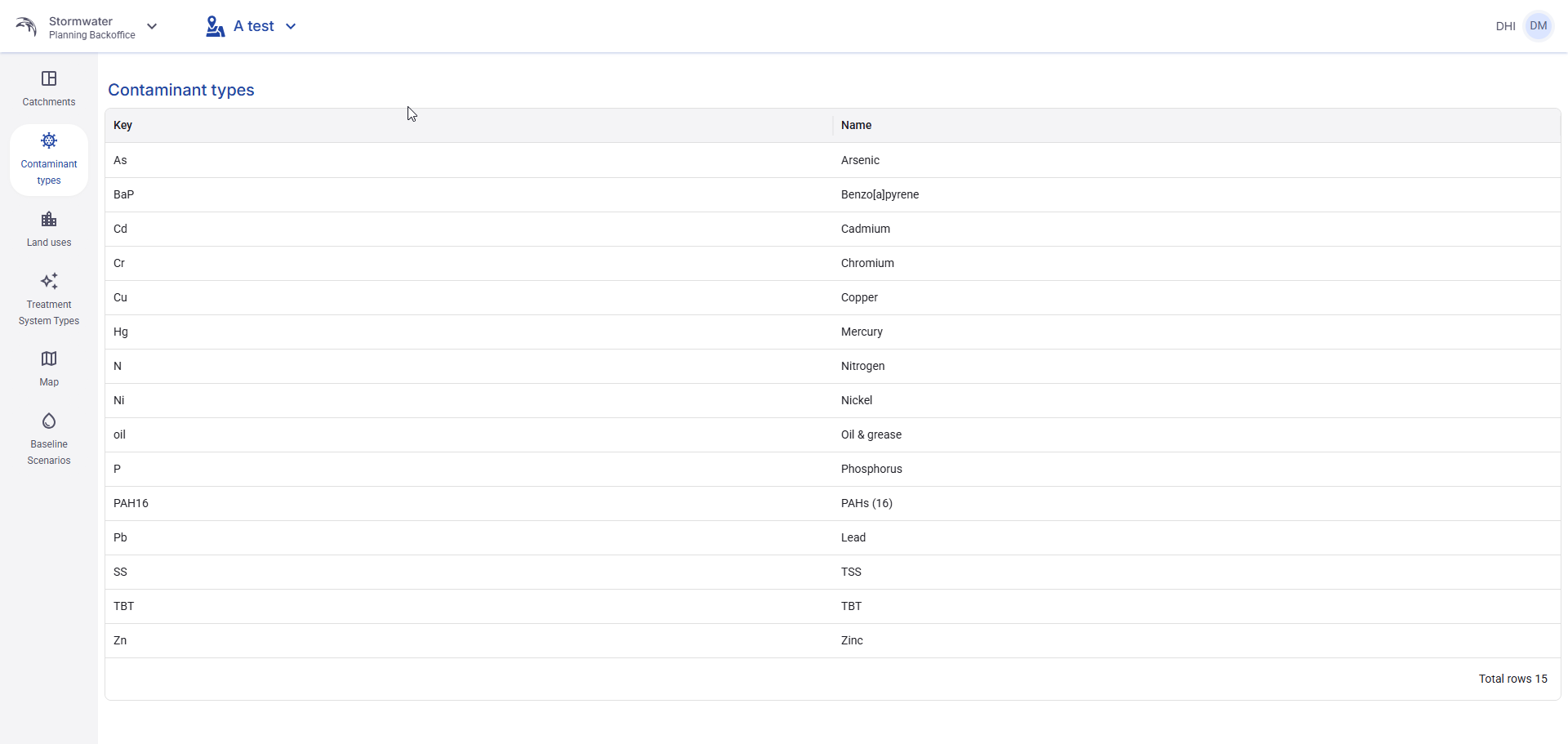
Figure 18. Contaminant types table.
5.3 Read-only behavior
This tab is read-only. The user cannot create, edit, delete, upload, download, or save anything in this view.
The tab is used only to review which contaminant types are currently available in the system.
5.4 Available contaminant types
In the current view, the following contaminant types are visible:
- As - Arsenic
- BaP - Benzo[a]pyrene
- Cd - Cadmium
- Cr - Chromium
- Cu - Copper
- Hg - Mercury
- N - Nitrogen
- Ni - Nickel
- oil - Oil & grease
- P - Phosphorus
- PAH16 - PAHs (16)
- Pb - Lead
- SS - TSS
- TBT - TBT
- Zn - Zinc
6. Land uses
6.1 Purpose of the Land uses tab
The Land uses tab is used to configure land use records and the contaminant values assigned to each record. This data is used later by the Stormwater Planning module.
6.2 Land uses overview
The tab contains a toolbar and a wide editable table.
The visible actions at the top of the tab are Download template, Upload, Save, and Delete all.
The table shows the land use records and the contaminant columns available in the system. The view also includes the standard table functions, such as Rows per page, page navigation, and horizontal scrolling when not all columns fit on the screen.
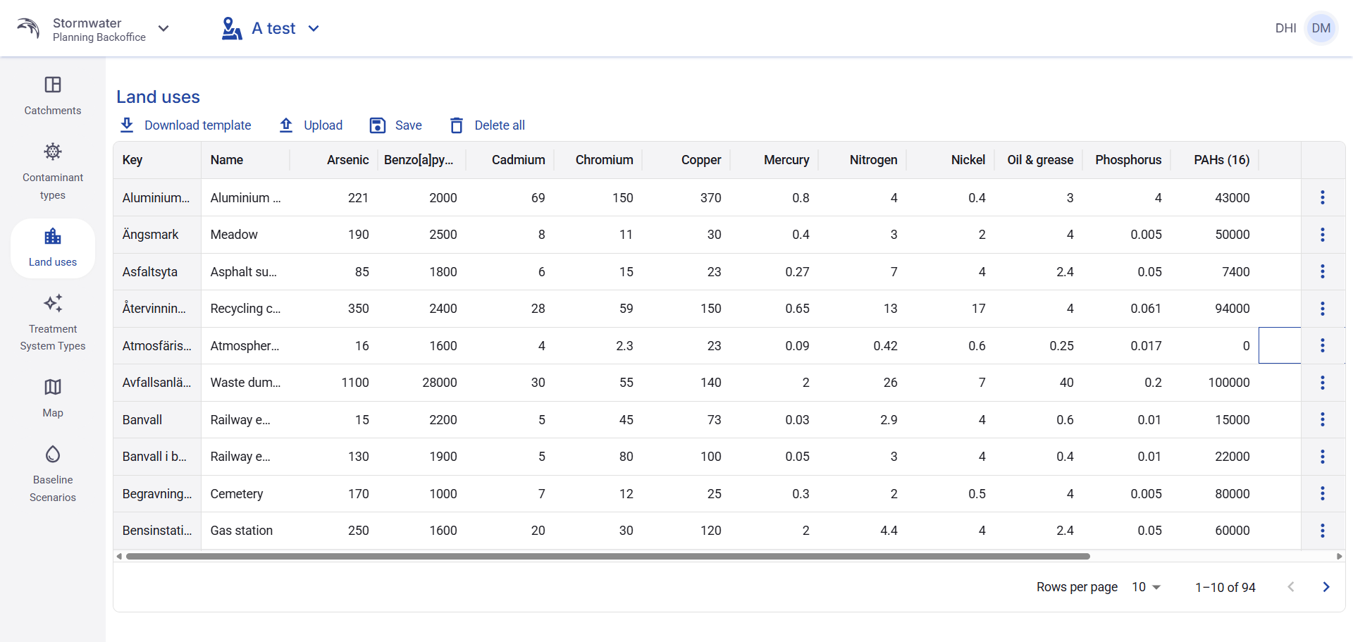
Figure 19. Land uses tab overview with toolbar, editable table, horizontal scroll bar, and page navigation.
6.3 Download template
To download an import template, click Download template.
The download window requires the user to select the file format before starting the download.
The visible formats in the interface are Csv, Xlsx, and Json.
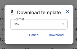
Figure 20. Download template dialog with Csv selected.
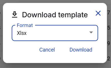
Figure 21. Download template dialog with Xlsx selected.
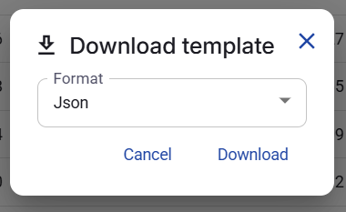
Figure 22. Download template dialog with Json selected.
6.4 Upload land uses
To import land use data, click Upload.
The upload window requires the user to select the file format and then choose the import file.
The visible formats in the interface are Csv, Xlsx, and Json.
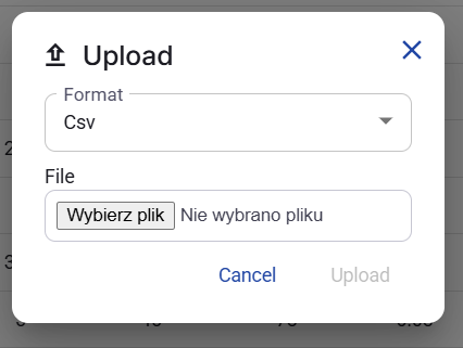
Figure 23. Upload dialog with Csv selected.
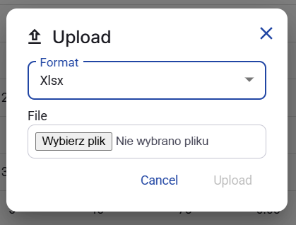
Figure 24. Upload dialog with Xlsx selected.
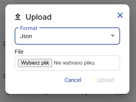
Figure 25. Upload dialog with Json selected.
6.5 Inline editing
The table supports inline editing. The user changes values directly in editable cells inside the table.
After a cell value is changed, the tab has pending changes that must be saved.
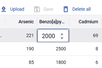
Figure 26. Example of inline editing in a land use table cell.
6.6 Save changes
After editing data inline, click Save to store the pending changes.
When there are no pending changes, the Save action is disabled. After a change is made, the Save action becomes active.
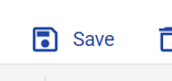
Figure 27. Save action shown as active after a table change.
6.7 Delete all land uses
The Delete all action removes all land use records from the table.
A confirmation dialog opens before the deletion is executed.
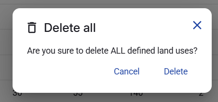
Figure 28. Delete all land uses confirmation dialog.
6.8 Delete a land use
Each land use row has a Delete action in its row context menu.
A confirmation dialog opens before the selected row is removed.
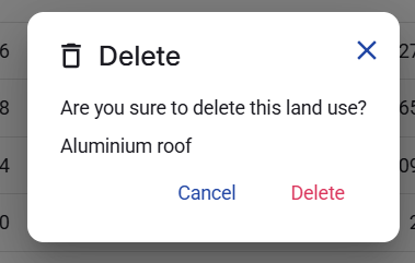
Figure 29. Delete land use confirmation dialog for a single row.
7. Treatment System Types
7.1 Purpose of the Treatment System Types tab
The Treatment System Types tab is used to manage treatment system groups and the treatment system types that belong to those groups. The contaminant values configured in this tab are part of the Stormwater Planning configuration used later in scenarios.
7.2 Treatment System Types overview
When the user opens the Treatment System Types tab, the left side shows the list of available treatment system groups together with the actions Download template and Upload.
At this stage, the main content area on the right side is empty until the user selects one group from the list on the left.
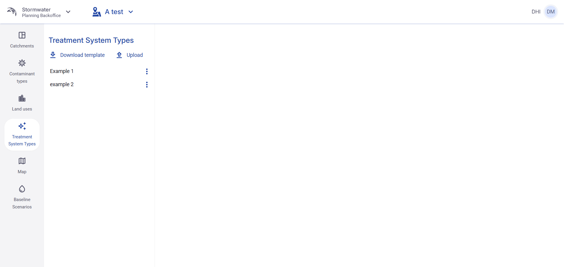
Figure 30. Treatment System Types tab overview before any group is selected.
7.3 Select a group to display treatment system types
To display the configured treatment system types, the user must first click one group in the left panel.
After one group is selected, the right side displays the Treatment System Types table for that group. The table contains one row per treatment system type and one contaminant column for each configured contaminant.
This view also shows the standard table functions, including horizontal scrolling, rows per page, and page navigation.
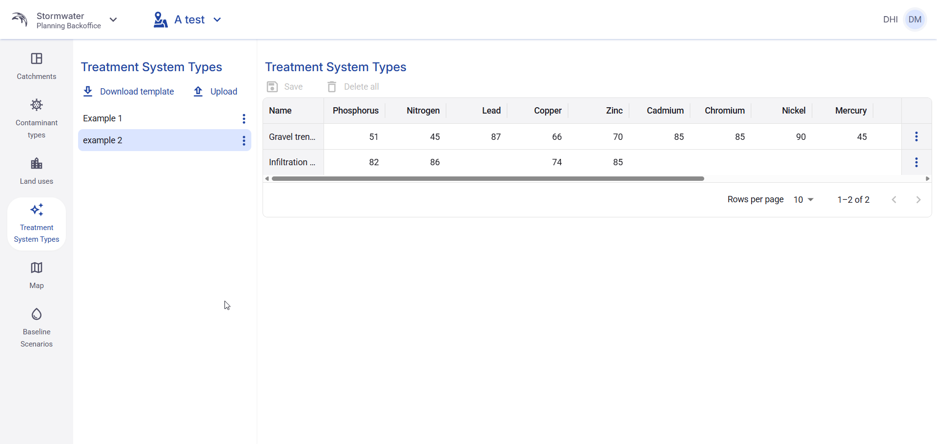
Figure 31. Treatment System Types view after a group is selected.
7.4 Download template
To download an import template, click Download template.
The dialog requires the user to select the file format before starting the download.
The visible formats in the interface are Xlsx, Csv, and Json.
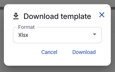
Figure 32. Download template dialog with Xlsx selected.
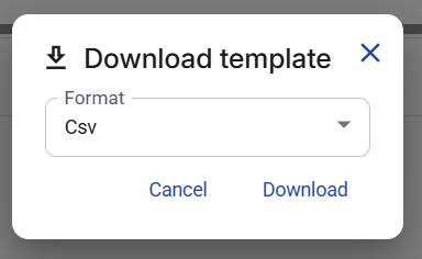
Figure 33. Download template dialog with Csv selected.
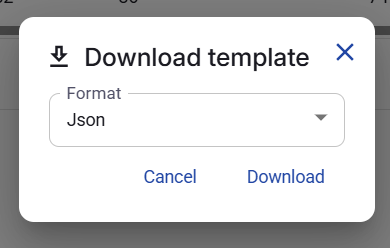
Figure 34. Download template dialog with Json selected.
7.5 Upload treatment system types
To import treatment system types, click Upload.
The upload dialog requires three inputs: Format, File, and Group name.
The visible formats in the interface are Csv, Xlsx, and Json.
Group name defines the name of the treatment system group that will be created or filled by the uploaded file.
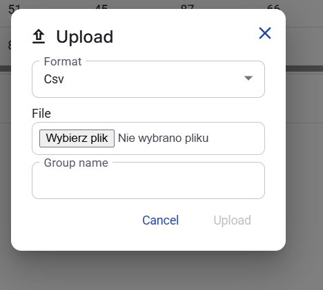
Figure 35. Upload dialog with Csv selected.
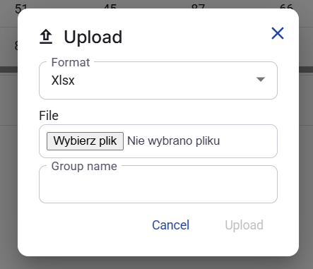
Figure 36. Upload dialog with Xlsx selected.
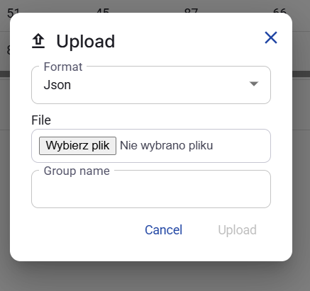
Figure 37. Upload dialog with Json selected.
7.6 Edit a group name
Each treatment system group in the left panel has a context menu.
The edit dialog allows the user to change the Name of the selected group.
The field shows a character counter in the same input control.
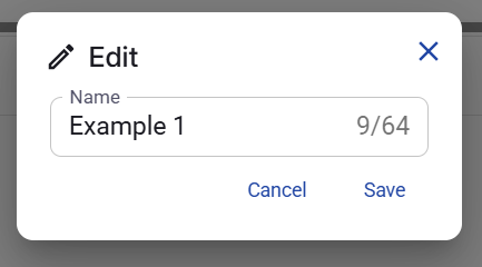
Figure 38. Edit group name dialog.
7.7 Inline editing
The contaminant values in the Treatment System Types table can be edited directly in the table.
The user changes a value inline inside the selected cell. The edited value stays pending until it is saved.
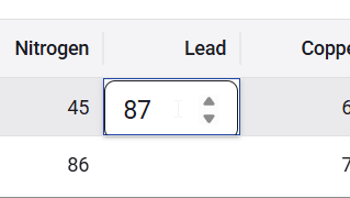
Figure 39. Example of inline editing in a treatment system type cell.
7.8 Save changes
After one or more contaminant values are edited inline, the user must click Save to store the pending changes.
The Save action is disabled when there are no pending changes. After an inline edit is made, the Save action becomes active.
This section documents only the Save action used after inline editing. Actions such as Delete all are visible in the interface but are not described here as active workflow steps for this manual version.
7.9 Delete a treatment system type
Each treatment system type row has a row context menu with a Delete action.
A confirmation dialog opens before the selected treatment system type is removed.

Figure 40. Delete treatment system type confirmation dialog.
8. Map
8.1 Purpose of the Map tab
The Map tab is used to create, upload, connect, disconnect, and manage the network objects shown on the planning map.
8.2 Map tab overview
The tab is divided into two main areas.
- The left panel contains the actions and filters used to work with map objects.
- The right side contains the map view.
The visible object sections in the left panel are General nodes, Reporting nodes, Discharge nodes, Treatment Nodes, Surfaces, and Polygons.
Surfaces are shown as a dedicated object category, but in the confirmed visible interface they are managed as a bulk layer, not as individually editable objects in the left panel.
The tab also shows the Create action, the Upload action with a dropdown menu, the Catchment selector, and the Subcatchment selector.
This section documents the confirmed visible behavior of the current Map tab and explains the visible object rules in UI language.
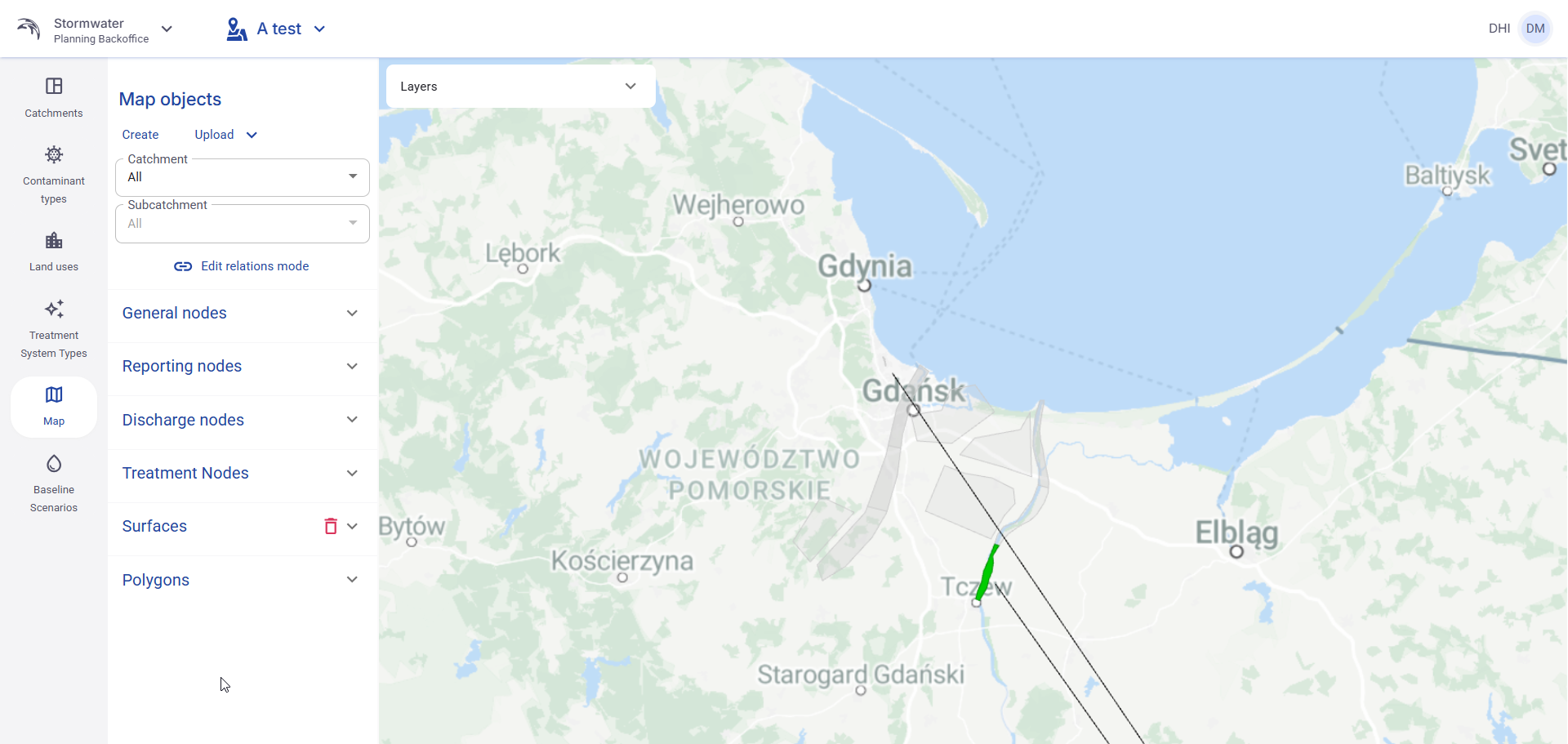
Figure 41. Map tab overview with actions, selectors, object sections, and map area.
8.3 Create a node
To create a new node, click Create. The application opens a creation panel.
In the creation panel, the user selects the node location by clicking Select and then clicking the required point on the map.
The basic visible fields in the standard creation panel are Longitude, Latitude, GisID, and Role.
The Role field determines which type of node is being created. In the confirmed screens, the visible standard roles are General node, Reporting node, and Discharge node.
A General node is a standalone object. It does not participate in Edit relations mode and cannot be connected to other objects.
Reporting nodes and Discharge nodes can be created without any connection. Their connections can be added later in Edit relations mode.
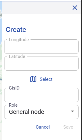
Figure 42. Create panel for a General node.
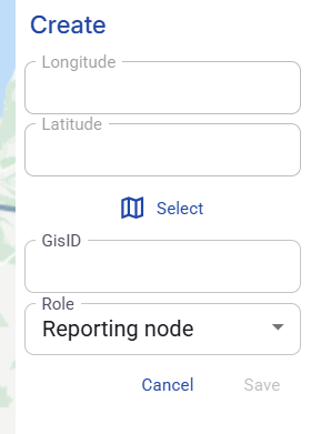
Figure 43. Create panel for a Reporting node.
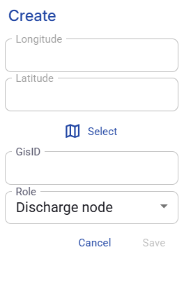
Figure 44. Create panel for a Discharge node.
8.4 Create a Treatment node
Treatment node creation contains more fields than the standard node creation panel.
In addition to the location fields and GisID, the user must also provide treatment-related values.
In the confirmed interface, the visible additional fields are Treatment type, Treatment system type, Treated subcatchment area, and Treatment node area.
The location of the Treatment node is also selected by clicking Select and then clicking the required point on the map.
A Treatment node cannot be created unless the user selects an existing Treatment system type.
A Treatment node also cannot be created unless the user selects an existing General polygon in the Treated subcatchment area field.
The Treatment node area field is optional. If the user fills it in, the selected object must also already exist as a General polygon.
These two polygon links are set directly in the Treatment node form. They are not created later through Edit relations mode.
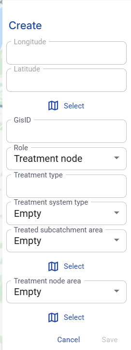
Figure 45. Create panel for a Treatment node.
8.5 Upload menu
The Upload action contains a dropdown menu. The confirmed upload options are General nodes, General polygons, and Surfaces.
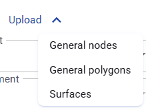
Figure 46. Upload menu in the Map tab.
8.6 Upload nodes
To upload nodes, open the Upload menu and choose General nodes.
The upload dialog requires the user to choose the import format and the file.
The confirmed visible formats are GeoJson and Shapefile zip.
Each upload dialog in this part of the Map tab also contains a Download template action.
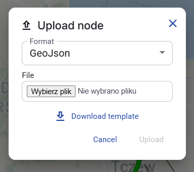
Figure 47. Upload node dialog with GeoJson selected.
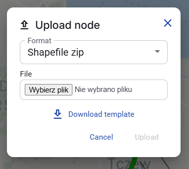
Figure 48. Upload node dialog with Shapefile zip selected.
8.7 Upload general polygons
To upload polygons, open the Upload menu and choose General polygons.
The upload dialog requires the user to choose the format and the file.
The confirmed visible formats are GeoJson and Shapefile zip.
General polygons are uploaded from a file. They are not created one by one by clicking on the map.
After upload, they enter the system as General polygon objects. A polygon can later change role only through the visible edit rules or through specific connection rules.
The dialog also contains a Download template action.
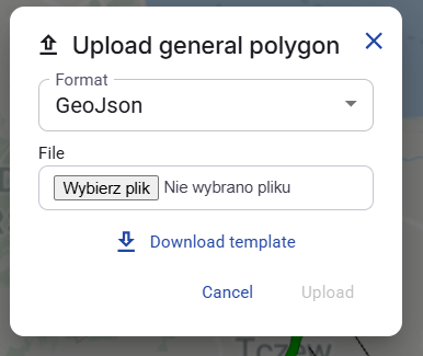
Figure 49. Upload general polygon dialog with GeoJson selected.
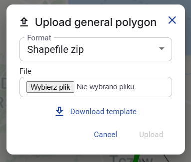
Figure 50. Upload general polygon dialog with Shapefile zip selected.
8.8 Upload surfaces
To upload surfaces, open the Upload menu and choose Surfaces.
The upload dialog requires the user to choose the format and the file.
The confirmed visible formats are GeoJson and Shapefile zip.
This dialog also contains a Download template action and an information panel that explains which identifying data must be included in the upload file.
The visible guidance explains that the file can be prepared as one large file for all catchments and all land uses, as a smaller file for one selected land use, as a smaller file for one selected subcatchment, or as a smaller file for one selected combination of subcatchment and land use.
The Surface upload action does not depend on the current Catchment or Subcatchment selection in the left panel. The identifying subcatchment information must be included in the upload file itself.
In the confirmed visible interface, surfaces are handled as a bulk workflow. The user can upload surfaces in bulk and remove all surfaces in one action, but the user cannot create, edit, or delete individual surfaces one by one from the interface.
The Surfaces section in the left panel is not an editable list of individual surface objects. It is used for visibility and bulk management only.
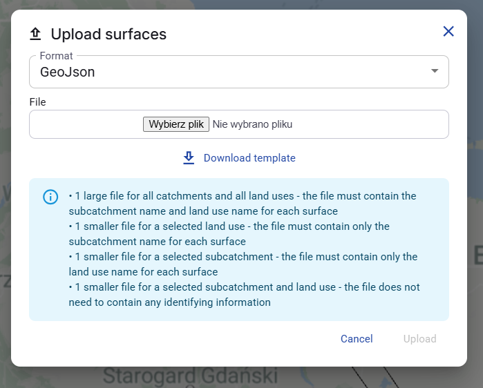
Figure 51. Upload surfaces dialog with GeoJson selected.
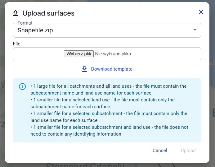
Figure 52. Upload surfaces dialog with Shapefile zip selected.
8.9 Catchment selector
The Catchment selector is visible in the left panel of the Map tab.
When Catchment is set to All, the current view is not limited to one catchment.
When a specific catchment is selected, the view is limited to that catchment and the Subcatchment selector becomes useful for the selected parent catchment.
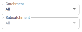
Figure 53. Catchment and Subcatchment selectors with Catchment set to All.
8.10 Subcatchment selector
The Subcatchment selector depends on the selected Catchment.
After the user selects a specific catchment, the Subcatchment dropdown shows All together with the subcatchments that belong to the selected catchment.
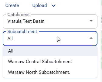
Figure 54. Subcatchment selector after a specific catchment is selected.
8.11 Layers panel
The Layers list allows the user to show or hide individual object layers on the map.
Each layer in the list has a checkbox. Selecting the checkbox shows that layer on the map. Clearing the checkbox hides it.
This makes it possible to focus only on the object types needed at the moment, for example nodes, surfaces, polygons, or relations.
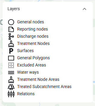
Figure 55. Layers list used to show or hide map layers.
8.12 Edit relations mode
Most map objects need to be connected to other objects in the network. For that reason, the Map tab includes Edit relations mode.
The Edit relations mode action opens the relation editing tools for creating or removing connections between objects.
This mode is used only for object types that support visible network connections. It is not used for every object shown on the map.
In the current visible behavior, there is no separate Save button for creating a connection. After the user selects a valid target object, the connection is sent immediately.
Figure 56. Edit relations mode action.
8.13 Linking and unlinking objects
After entering relation editing mode, the user can choose either linking mode or unlinking mode.
In the current interface, the following connections are available in Edit relations mode:
- Treatment node to Treatment node.
- Treatment node to Discharge node.
- Discharge node to Reporting node.
- Reporting node to Reporting node.
- General polygon to Reporting node. After this connection is created, the polygon becomes a Water way segment.
- Water way segment to Reporting node.
The following objects do not participate in Edit relations mode: General node, Excluded area, Treatment node area, and Treated subcatchment area.
Treatment node area and Treated subcatchment area are assigned from the Treatment node form, not from the relation editor.
A Water way segment does not need to be connected to a Reporting node in order to exist. It can remain on the map without that connection.
In linking mode, the user clicks one object on the map first. After that, the application greys out the objects that cannot be connected to the selected object.
In the confirmed visible frontend behavior, disconnecting a Treatment node area from a Treatment node removes the relation from the Treatment node side only. The polygon is not immediately converted back to General polygon by the frontend.
The user then clicks a second compatible object to create the relation.
In unlinking mode, the user removes an existing relation instead of creating a new one.
When a Water way segment is disconnected from a Reporting node, it returns to the General polygon role in the visible frontend behavior.

Figure 57. Relation editing toolbar with link and unlink modes.
8.14 Link confirmation dialog
When the user selects two compatible objects in linking mode, the application can display a confirmation dialog asking whether the relation should be created.
The user can continue by clicking Connect or stop the action by clicking Cancel.
If the user selects Don't show again, the confirmation is skipped for the rest of the current user session only. It is not a permanent system setting.
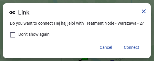
Figure 58. Link confirmation dialog.
8.15 Delete all surfaces
In the confirmed visible interface, there is no separate action for creating, editing, or deleting one individual surface. The surface workflow available to the user is bulk upload and Delete all.
The user can remove all imported surfaces from the system at once.
The delete action is available in the Surfaces section of the left panel.
Before the deletion is executed, the application displays a confirmation dialog.
In the current interface, there is no separate action for creating, editing, or deleting one individual surface. The surface workflow available to the user is bulk upload and Delete all.
Delete all surfaces removes all imported surfaces from the current system view at once. There is no visible filter in this dialog for deleting only one surface or one smaller subset of surfaces.
Figure 59. Delete all action in the Surfaces section.
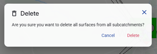
Figure 60. Delete all surfaces confirmation dialog.
8.16 Invalid configuration indicator
For many objects, the application shows a warning indicator when the object is not fully configured or is configured incorrectly.
The indicator appears as a red symbol next to the object name. Hovering over the warning shows additional information, for example Invalid state.
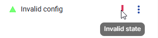
Figure 61. Invalid configuration indicator shown next to an object.
8.17 Polygon visibility
The Polygons section allows the user to control the visibility of polygon categories on the map.
Each polygon category has its own checkbox. Selecting a checkbox shows that category on the map. Clearing the checkbox hides it.
This control can be used for categories such as General polygon, Excluded area, Water way segment, Treatment node area, and Treated subcatchment area.
This section controls category visibility only. It does not edit the role of an object and it does not create or remove relations.
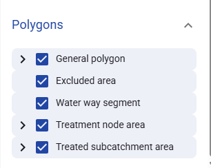
Figure 62. Polygon categories with visibility checkboxes.
8.18 Edit or delete map objects
The context menu of an object can be used to edit that object or delete it.
Editing is available for different object types. The fields shown in the edit panel depend on the selected object type.
For polygon objects, the role selector can be edited only where the interface allows it. In the current interface, a polygon can be edited as General polygon, Water way segment, or Excluded area when that selector is available.
Treatment node area and Treated subcatchment area are locked roles. Their role selector is not available for changing in the edit panel.
Deleting a node or polygon is done from its context menu. The visible manual should describe the confirmation dialog and the direct delete action, but should not promise any cascade effects that are not shown in the UI.
The examples below show the edit behavior for polygon-based objects and related map objects.

Figure 63. Context menu for a polygon object with Edit and Delete actions.
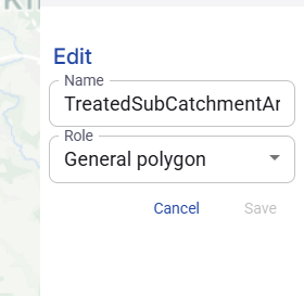
Figure 64. Edit general polygon window.
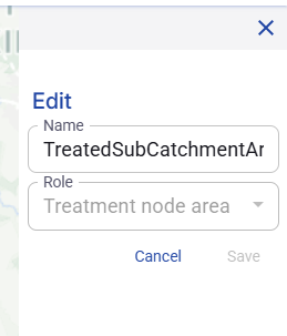
Figure 65. Edit treatment node area window.
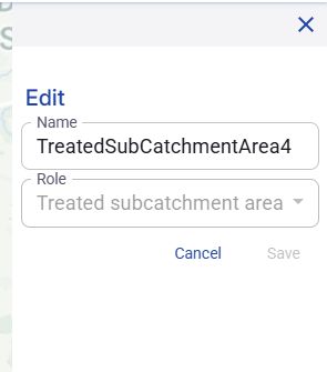
Figure 66. Edit treated subcatchment area window.
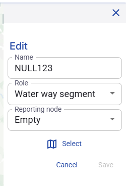
Figure 67. Edit water way segment window.
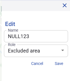
Figure 68. Edit excluded area window.
9. Baseline scenarios
9.1 Purpose of the Baseline scenarios tab
The Baseline scenarios tab is used to import rainfall data, define rainfall event detection rules, calculate a baseline scenario, and then create Treatment Scenarios based on that baseline scenario.
9.2 Baseline scenarios overview
The Baseline scenarios tab is divided into two main working areas.
- The left panel contains the list of available baseline scenarios and the actions related to them.
- The right side shows the Treatment Scenarios that belong to the currently selected baseline scenario.
- When a Treatment Scenario is selected, the same area also shows a map preview, a list of Treatment Nodes, and an Excluded Areas tab.
Each baseline scenario also shows its calculation status. A newly created baseline scenario is shown with the status New.
The Commit state action is visible in this tab because the scenario calculations depend on the currently committed Planning Backoffice configuration. If the system shows unsaved changes, the user should commit the configuration before running calculations.
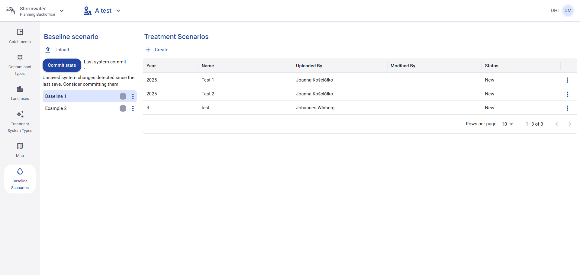
Figure 69. Baseline scenarios overview with the baseline list, Commit state action, and Treatment Scenarios table.
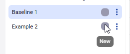
Figure 70. Example of the baseline scenario status shown as New.
9.3 Upload a baseline scenario
To create a new baseline scenario, click Upload in the Baseline scenario section.
The upload window contains the following fields:
- Name - the user-defined scenario name.
- Format - the file format used for the import.
- File - the rainfall time series file to upload.
- Dry Gap Period - the minimum dry period used to split rainfall into separate rainfall events.
- Rain Volume Threshold - the minimum rain volume required for an event to be kept in the scenario.
After all required fields are filled in, click Upload to create the baseline scenario.
Figure 71. Upload action in the Baseline scenario section.
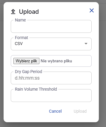
Figure 72. Upload baseline scenario dialog.
9.4 How rainfall events are created during baseline import
During the baseline import, the system groups rainfall into separate rainfall events.
- Rainfall is summed into events based on the uploaded rainfall time series.
- If the dry period between rainfall blocks is longer than the Dry Gap Period, the next rainfall starts a new event.
- If a single rainfall event is smaller than the Rain Volume Threshold, that event is ignored and is not included in the scenario.
These settings are used only to define which rainfall events are kept in the imported baseline scenario.
9.5 Baseline scenario actions
Open the context menu for a baseline scenario to access the available actions.
- Download - downloads the rainfall time series stored for that baseline scenario.
- Run - starts the baseline calculation. This action is available only when the configuration is valid.
- Edit - allows the user to change the scenario name.
- Delete - removes the selected baseline scenario.
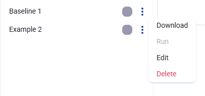
Figure 73. Baseline scenario context menu with Download, Run, Edit, and Delete actions.
The Edit action opens a simple window where only the scenario name can be changed.
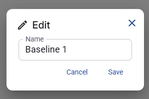
Figure 74. Edit baseline scenario dialog.
The Delete action opens a confirmation window before the scenario is removed.
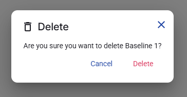
Figure 75. Delete baseline scenario confirmation dialog.
9.6 Treatment Scenarios overview
After a baseline scenario is selected, the Treatment Scenarios linked to that baseline scenario are shown on the right side.
The table displays the main descriptive fields for each Treatment Scenario, including Year, Name, Uploaded By, Modified By, and Status.
The user must first select a baseline scenario before working with its Treatment Scenarios.
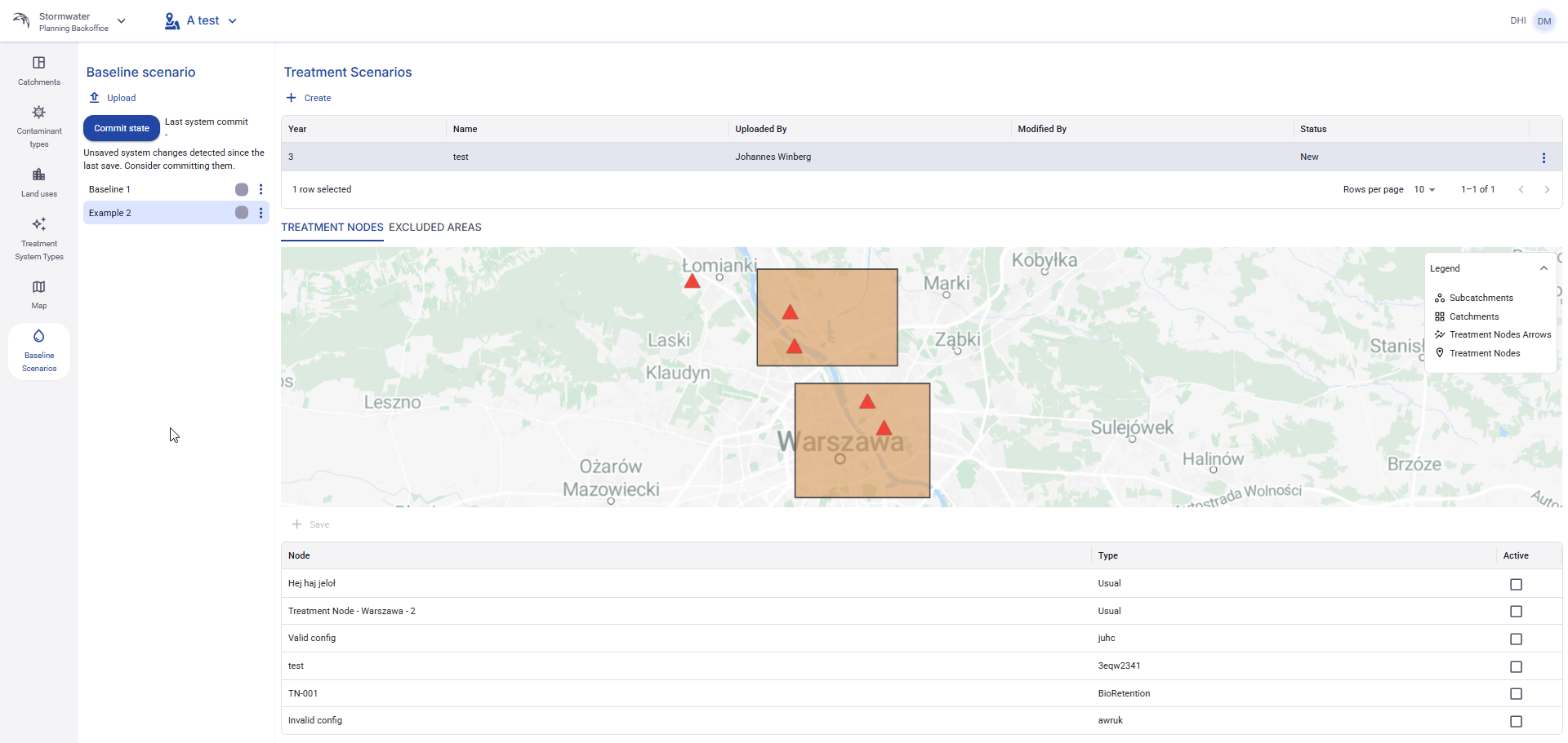
Figure 76. Selected Treatment Scenario view with the map, Treatment Nodes tab, and node activation table.
9.7 Create a Treatment Scenario
To create a new Treatment Scenario, click Create in the Treatment Scenarios section.
The creation window contains two descriptive fields:
- Year - a descriptive year field.
- Name - a descriptive scenario name.
These fields are used to identify the Treatment Scenario.
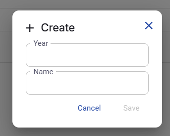
Figure 77. Create Treatment Scenario dialog.
9.8 Edit a Treatment Scenario
A Treatment Scenario can be renamed or updated from its context menu. The edit window allows the user to change the Year and Name fields.
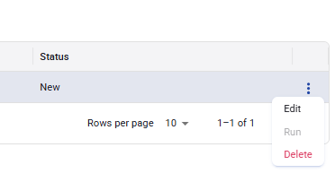
Figure 78. Treatment Scenario context menu with Edit, Run, and Delete actions.
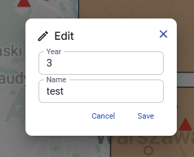
Figure 79. Edit Treatment Scenario dialog.
9.9 Delete a Treatment Scenario
The Delete action removes the selected Treatment Scenario after confirmation.
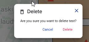
Figure 80. Delete Treatment Scenario confirmation dialog.
9.10 Run a Treatment Scenario
Use the Run action in the Treatment Scenario context menu to start the calculation for the selected Treatment Scenario.
This action uses the currently selected baseline scenario together with the active Treatment Nodes and the selected Excluded Areas.
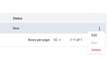
Figure 81. Run action in the Treatment Scenario context menu.
9.11 Activate or deactivate Treatment Nodes
When a Treatment Scenario is selected, the Treatment Nodes tab is shown under the map.
This table lists all Treatment Nodes available in the system. The Active checkbox is used to include or exclude a Treatment Node from the selected Treatment Scenario.
- A checked Active box means that the Treatment Node is enabled for this Treatment Scenario.
- A cleared Active box means that the Treatment Node is disabled for this Treatment Scenario.
- Changes are saved immediately. The user does not need to click Save.
The map preview helps the user understand the node configuration.
- Green Treatment Nodes on the map are active in the selected Treatment Scenario.
- Red Treatment Nodes on the map are inactive in the selected Treatment Scenario.
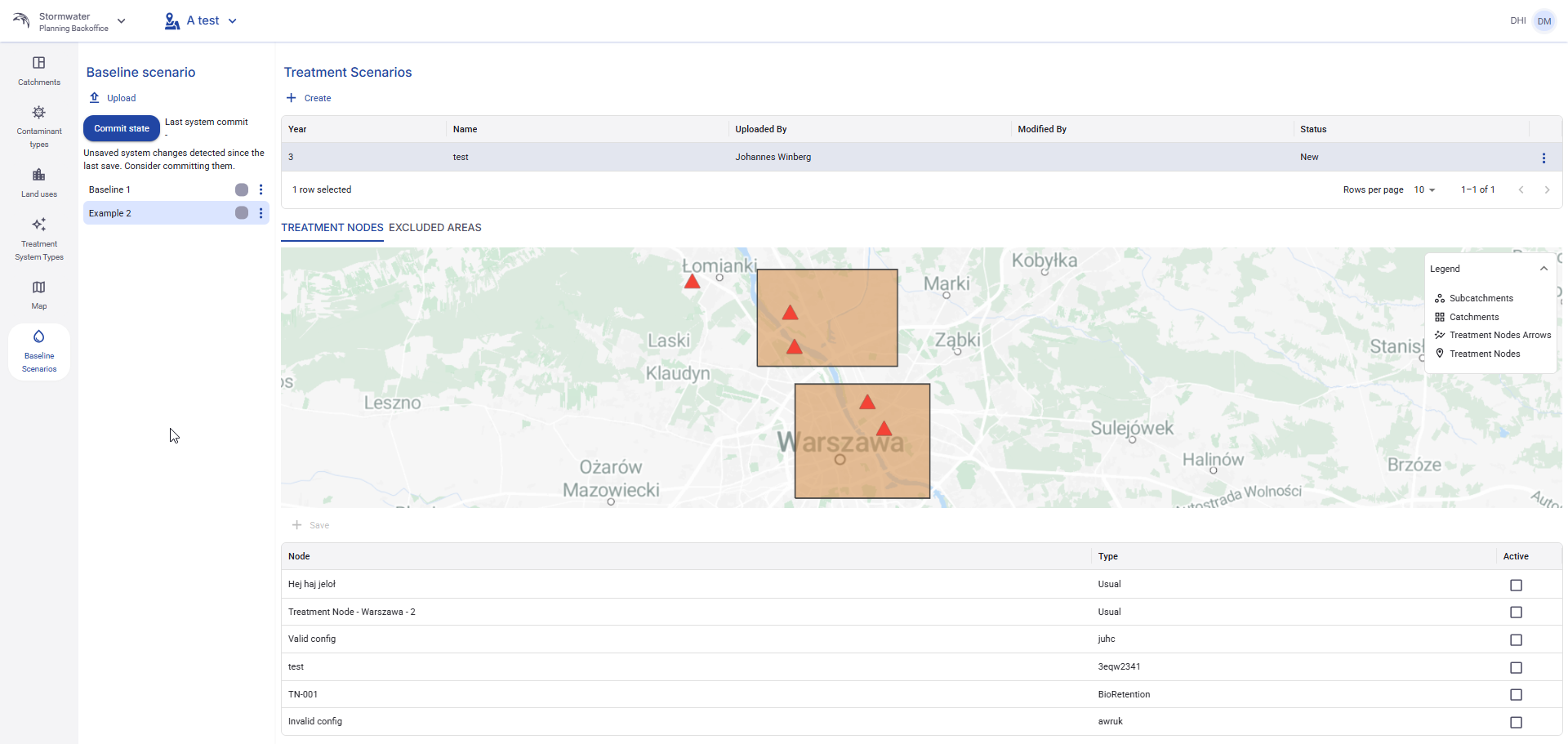
Figure 82. Treatment Nodes tab with the Active checkboxes and the map preview.
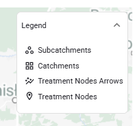
Figure 83. Legend used in the Treatment Scenario map preview.
9.12 Excluded areas in a Treatment Scenario
The Excluded Areas tab is used to remove selected surfaces from the calculation.
Areas marked in this tab do not produce surface runoff during the calculation for the selected Treatment Scenario.
As in the Treatment Nodes tab, activation or deactivation is saved immediately. No separate Save action is required.
9.13 Scenario status
Each baseline scenario shows its current calculation status in the left panel.
The default status for a newly created baseline scenario is New. This helps the user identify scenarios that have been created but not yet processed.
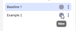
Figure 84. Baseline scenario status shown next to the scenario name.